Ei hakka oma kirjavahetust selle mudeli loojatega (Frans Hollandist, Jeremy USAst) eestindama. Samuti ei aja taga oxfordi inglist – pigem inf ja pildid.

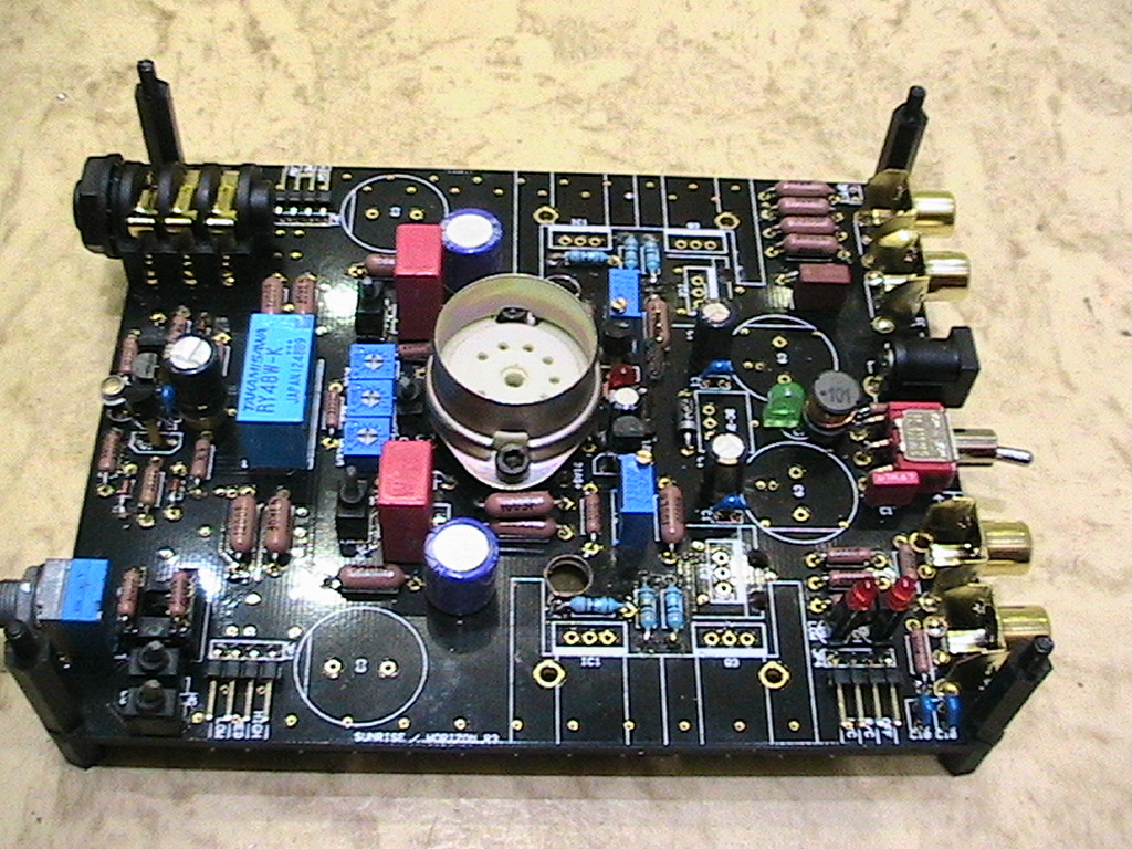
* Installed supercharger (tube heater 6,3V 1,1A) into Horizon amp.
To get underside to change power capacitors, I drilled holes and bolted the supercharger to PCB.
* Default inductive coil (100uH) changed for bigger current – 1,2A.
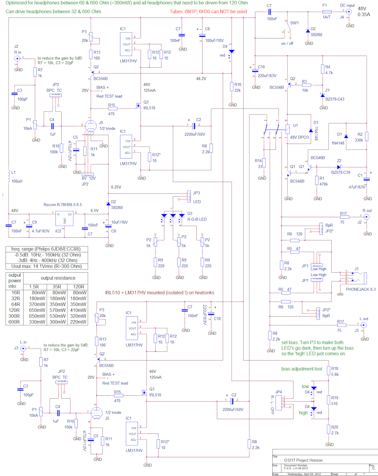
* Current for Mosfets changed higher from original 125mA to 150mA. Changed nominals of resistors for LM317HV – default 10+10 in parallel =5 ohms and 10 ohms. Now they are all 8,2ohms.
* Heatsinks larger – triple big heatsinks joined together with aluminium plates and 2x bigger heatsinks for separate LM317HV.
* Power capacitors are only 82uF100V, changed to 680uF63V 18x20mm. Problem is with input power/current rush when switching on the amp.
Default switch melted. Solved with double 120V5A On-Off-On switches to get mechanical soft-start. Now starting is through first switch 27ohms+alarm/buzzer and second switch will be contacted after it directly.
* Ventilation holes are drilled near heatsinks through PCB.
* Default Mosfet IRL510 (input capacitance 640pF measured) changed to Toshiba 2SK2013 (input capacitance 360pF measured).
* Grid capacitor was 470uF 10V now 680uF 6,3V Sanyo OS-Con.
* Tube plate current stabilizing red led -original(s) were 1,9V measured, I put 1,6V.
* Input default pot 10 Kohms changed to 47 Kohms.
* Input default capacitors 1uF changed to Wima10uF63V.
* Tube socket changed to Sovjet Mil with aluminium tube cover/shield.
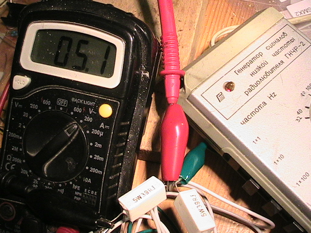
Measured the power output (LM317HV 8,2 ohm resistors, headphone dummy(s) 39ohm, output switch on low (1,5ohms), 30Hz generator+voltmeter).
Result is 5,1 volts sine = 650mW.

Temperature on big heatsinks under 60C, on little heatsinks under 70C.
https://ep1.pinkbike.org/p5pb15178515/p5pb15178515.jpg


* Installed supercharger (tube heater 6,3V 1,1A) into Horizon amp.
To get underside to change power capacitors, I drilled holes and bolted the supercharger to PCB.
* Default inductive coil (100uH) changed for bigger current – 1,2A.
* Current for Mosfets changed higher from original 125mA to 150mA. Changed nominals of resistors for LM317HV – default 10+10 in parallel =5 ohms and 10 ohms. Now they are all 8,2ohms.
* Heatsinks larger – triple big heatsinks joined together with aluminium plates and 2x bigger heatsinks for separate LM317HV.
* Power capacitors are only 82uF100V, changed to 680uF63V 18x20mm. Problem is with input power/current rush when switching on the amp.
Default switch melted. Solved with double 120V5A On-Off-On switches to get mechanical soft-start. Now starting is through first switch 27ohms+alarm/buzzer and second switch will be contacted after it directly.
* Ventilation holes are drilled near heatsinks through PCB.
* Default Mosfet IRL510 (input capacitance 640pF measured) changed to Toshiba 2SK2013 (input capacitance 360pF measured).
* Grid capacitor was 470uF 10V now 680uF 6,3V Sanyo OS-Con.
* Tube plate current stabilizing red led -original(s) were 1,9V measured, I put 1,6V.
* Input default pot 10 Kohms changed to 47 Kohms.
* Input default capacitors 1uF changed to Wima10uF63V.
* Tube socket changed to Sovjet Mil with aluminium tube cover/shield.
Measured the power output (LM317HV 8,2 ohm resistors, headphone dummy(s) 39ohm, output switch on low (1,5ohms), 30Hz generator+voltmeter).
Result is 5,1 volts sine = 650mW.

Temperature on big heatsinks under 60C, on little heatsinks under 70C.
https://ep1.pinkbike.org/p5pb15178515/p5pb15178515.jpg


Comment